前言

  最近这段时间,场景模型那边给我提需求
  希望我可以开发一个工具来简化 Max 工具挤出的问题。
  最初这是什么情况我也不太了解。

  于是我去到工位上了解才明白,原来是需要基础场景模型的轮廓。
  由于项目是横版格斗类型,用引擎制作背景的轮廓比较消耗资源。
  传统制作外轮廓的方案是复制一个新的模型放大,但是这回导致面数翻倍。
  而这里恰巧是横版格斗,背景的视角不会有太大的运动,因此人工制作特定视角的轮廓模型是可行的。

  因此制作人员只是想要简化Max在poly模式下挤出会有多余边面产生的问题。
  不过考虑到整一个轮廓的效果,我在想Maya貌似有工具是可以直接生产的,未必就需要手工制作轮廓。

  后来翻了一下,找到 Toon 材质里面的确有制作轮廓的 PaintEffect 效果

PaintEffect研究

  通过 Toon 下的 轮廓生成真的非常省心,不用考虑如何根据当前视角获取物体轮廓的问题了。

alt
alt

  只可惜生成的模型是一管道的效果,而制作那边所希望的是面片就够了。

  于是我进行了进一步的研究,如何将 PaintEffect 的效果转换为面片。

  经过我自己简单的研究,我发现可以通过 PaintEffect 转曲线获取到模型的轮廓曲线。
  进而通过扩张曲线放样可以生成出想要的面片模型。

alt

轮廓生成 代码探究

  首先需要生成 PaintEffect 的轮廓模型的代码。
  这一步可以参照脚本编辑器的代码回显。

1
assignNewPfxToon;

  执行这个命令有个缺点就是无法返回 PaintEffect 生成的轮廓节点,虽然执行会选中这个节点,可以通过 ls -sl 进一步获取,但是还是想更加优雅一点
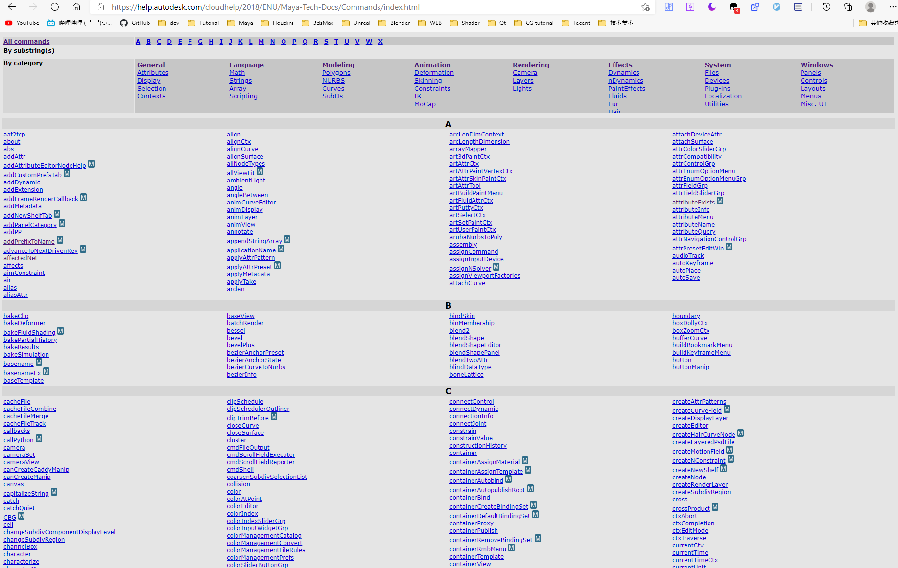
  通过 whatIs 命令可以查看一下内置脚本的代码

1
2
whatIs assignNewPfxToon;
// Result: Mel procedure found in: C:/Program Files/Autodesk/Maya2018/scripts/paintEffects/assignNewPfxToon.mel //

  打开上面路径的脚本

1
2
3
4
global proc assignNewPfxToon()
{
assignPfxToon "" 0;
}

  套娃警告!还是需要查询一下 assignPfxToon 代码

1
2
whatIs assignPfxToon;
// Result: Mel procedure found in: C:/Program Files/Autodesk/Maya2018/scripts/paintEffects/assignPfxToon.mel //

  继续打开脚本查看源码
  我看到里面的代码相当的复杂,判断的情况也比较多,于是放弃再进一步抽丝剥茧了。
  还是用 ls -sl 好了


  获取到轮廓模型之后,后面需要将 paintEffects 转换为 曲线。

alt

  这一步操作就非常不友好了,既没有返回曲线也没有选择到曲线,我就没办法获取到转换的曲线了。
  于是还是的找到转换曲线的命令去翻一下 mel 里面的代码

1
2
3
4
doPaintEffectsToCurve( 0);
// Result: 1 //
whatIs doPaintEffectsToCurve;
// Result: Mel procedure found in: C:/Program Files/Autodesk/Maya2018/scripts/paintEffects/doPaintEffectsToCurve.mel //

  可以看到执行代码 执行了 doPaintEffectsToCurve 函数
  于是去找 doPaintEffectsToCurve 的mel源码

1
2
3
4
5
6
7
8
9
10
11
12
global proc int doPaintEffectsToCurve( int $hideStrokes )
{
int $vertColorMode = 0;
int $quadOutput = 0;
int $polyLimit = 100000;
int $doHistory = `constructionHistory -q -tgl`;

int $status = doPaintEffectsToGeom( $doHistory, $vertColorMode,
$quadOutput, $hideStrokes, $polyLimit, 2);
return $status;
}

  再次套娃警告!!

1
2
whatIs doPaintEffectsToGeom;
// Result: Mel procedure found in: C:/Program Files/Autodesk/Maya2018/scripts/paintEffects/doPaintEffectsToGeom.mel //

  再次翻源码,这里的代码可就复杂多了。
  但是这次没法省事,如果不高清楚这里的曲线生成方式,就没办法获取生成的曲线。
  我只好捋一捋这里生成逻辑,将无关的部分屏蔽掉。

alt

  很好下面一步就是查找一下 createPfxOutCurves 的源码

1
2
whatIs createPfxOutCurves;
// Result: Mel procedure found in: C:/Program Files/Autodesk/Maya2018/scripts/paintEffects/createPfxOutCurves.mel //

  核心打开抽出来之后其实一切都很清晰了。

alt

   pfxToon 节点会输出 outMainCurves 属性,里面存储了当前轮廓下的曲线形态。
  将这个属性连接到 nurbscurve 节点的 create 属性上就可以生成轮廓曲线了。
  于是我将这个操作抽离出一个函数

1
2
3
4
5
6
7
8
9
10
11
12
13
def generateProfileCurve(profile_node):
count = profile_node.outMainCurveCount.get()
crv_list = []
for i in range(count):
attr = profile_node.outMainCurves[i]
if pm.connectionInfo(attr,isSource=1):
continue
crv = pm.createNode("nurbsCurve")
pm.connectAttr(attr,"%s.create"%crv,f=1)
# NOTE 断开连接
attr.disconnect(crv.create)
crv_list.append(crv.getParent())
return crv_list

  如此一来总算是可以通过代码获取到生成的对应轮廓曲线,断开连接可以确保生成出当前摄像机轮廓的曲线效果,而不是实时生成。

扩大曲线

  现在已经有了当前轮廓的曲线,怎么才能沿着曲线外围方向挤压出面片呢?
  当时首先想到的是使用曲面的挤压命令,然而挤压命令的朝向是固定方向的,无法控制沿着曲线表面的法线方向扩张。
  后来搞了好久都没有搞出来,只好用放样(loft)的来做面片了。

  只需要再将轮廓曲线放大一下就可以有两条曲线通过放样生成面片。
  然而如何生成扩大的曲线也难倒我了。

  我最初的想法是将模型沿着法线方向扩大,生成新的轮廓,然后再缩小回去。
  这样就有了一一对应的轮廓曲线。

1
2
3
4
5
6
7
8
9
10
11
12
13
14
15
16
17
18
19
20
21
22
23
import maya.api.OpenMaya as om
def inflateMesh(mesh,scale=1):

sel_list = om.MSelectionList()
sel_list.add(str(mesh))

DagPath,Obj = sel_list.getComponent(0)

Mesh = om.MFnMesh(DagPath)
MeshPoints = Mesh.getPoints(om.MSpace.kWorld)
newMeshPoints = om.MFloatPointArray()

for i in range(len(MeshPoints)):
MeshPointNormal = Mesh.getVertexNormal(i , om.MSpace.kWorld)

x = MeshPoints[i].x + MeshPointNormal.x * scale
y = MeshPoints[i].y + MeshPointNormal.y * scale
z = MeshPoints[i].z + MeshPointNormal.z * scale
newMeshPoint = om.MFloatPoint(x,y,z)

newMeshPoints.append(newMeshPoint)

Mesh.setPoints(newMeshPoints, om.MSpace.kWorld)

  上面的代码就可以实现模型沿着法线放大,但是经过我调试之后我发现不对。
  模型放到之后的轮廓数量可能和之前是不一样的,导致生成的曲线根本就对不上。

  后来想到应该让曲线沿着法线方向扩大就好了。
  于是我通过法线上的 CV 点获取到 CV 点到曲线上的 法线值
  通过这个法线值可以利用扩大模型的方法来扩大曲线。
  然而我发现这样还是不对,CV获取到的法线运动有时候并不是我所预期的。


  后来我仔细想了一下,法线可以通过 CV 点获取模型上的法线值
  这样扩大出来的效果应该是我所预期的法线了。

1
2
3
4
5
6
7
8
9
10
11
12
13
14
15
16
17
18
19
20
21
22
23
24
25
26
27
28
29
30
31
32
33
34
35
import maya.api.OpenMaya as om
def inflateCurveOnMesh(crv,mesh,scale=1):

newCrv = pm.duplicate(crv)[0]

sel_list = om.MSelectionList()
sel_list.add(str(crv))
sel_list.add(str(mesh))
sel_list.add(str(newCrv))

DagPath,_ = sel_list.getComponent(0)

Curve = om.MFnNurbsCurve(DagPath)
CurveCVs = Curve.cvPositions(om.MSpace.kWorld)
newCurveCVs = om.MPointArray()

DagPath,_ = sel_list.getComponent(1)
Mesh = om.MFnMesh(DagPath)
DagPath,_ = sel_list.getComponent(2)
newCurve = om.MFnNurbsCurve(DagPath)

for i in range(len(CurveCVs)):
cv = CurveCVs[i]

normal,_ = Mesh.getClosestNormal(cv)

x = cv.x + normal.x * scale
y = cv.y + normal.y * scale
z = cv.z + normal.z * scale
newCurveCV = om.MPoint(x,y,z)

newCurveCVs.append(newCurveCV)

newCurve.setCVPositions(newCurveCVs)
return newCrv

  输入轮廓法线和模型就可以通过API生成一条扩大的曲线。

曲线放样

  下面就需要调整曲面转换成poly的参数,确保生成面数少而简洁的模型效果。

alt

  代码转换如下

1
2
3
4
5
6
pm.nurbsToPolygonsPref(polyType = 1)
pm.nurbsToPolygonsPref(format = 2)
pm.nurbsToPolygonsPref(uType = 3)
pm.nurbsToPolygonsPref(uNumber = 1)
pm.nurbsToPolygonsPref(vType = 3)
pm.nurbsToPolygonsPref(vNumber = 1)

  当时也是完全不知道有 nurbsToPolygonsPref 的命令
  因此我测试的时候完全没有发现这里设置参数的问题,结果上了制作的电脑之后,发现转换的模型效果不对。
  于是我才去研究 loft 窗口下的 polygon 转换是怎么实现的。

1
2
3
4
5
6
7
8
9
10
11
// loft 窗口打开代码回显
LoftOptions;
loftToolScript 3;

whatIs LoftOptions;
// Result: Run Time Command //
runTimeCommand -q -c LoftOptions;
// Result: loftToolScript 3 //

whatIs loftToolScript;
// Result: Mel procedure found in: C:/Program Files/Autodesk/Maya2018/scripts/others/loftToolScript.mel //

  runTimeCommand 可以查到命令真实执行的代码是什么,其实就是第二行回显的代码
  下面可以去找 loftToolScript.mel 查看模型的代码是怎么实现的。

alt

1
2
3
4
whatIs scriptToolScript;
// Result: Mel procedure found in: C:/Program Files/Autodesk/Maya2018/scripts/others/scriptToolScript.mel //
whatIs performLoft;
// Result: Mel procedure found in: C:/Program Files/Autodesk/Maya2018/scripts/others/performLoft.mel //

  我发现 scriptToolScript 是执行了传进去的字符串,因此 performLoft 的代码才是重点。

alt

  由此我们可以逐渐找到生成 loft 选项框窗口的代码 loftOptions。

alt

  保持代码追踪最后会发现点击 polygon 窗口的时候回调用到 nurbsToPolyAddOptions 生成 NURBS 转 poly 的选项

1
2
3
4
whatIs nurbsToPolyAddOptions;
// Result: Mel procedure found in: C:/Program Files/Autodesk/Maya2018/scripts/others/nurbsToPolyAddOptions.mel //
whatIs nurbsToPolygonsPref;
// Result: Command //

  在里面的代码中我又找到了 nurbsToPolygonsPref 的命令
  这个命令就是 Mel 内置用来设置 NURBS转Polygon 的参数命令了
  于是我就可以通过开头的代码来实现转换参数的调整。

代码总结

  基本上上述的部分就是这个轮廓挤出的难点所在。
  代码可以参照 https://github.com/FXTD-ODYSSEY/MayaScript/blob/430e9194da85d884d0304b141706bae44460dd8a/model/outline/test_outline.py
  另外我也写了个带GUI调整的代码 https://github.com/FXTD-ODYSSEY/MayaScript/blob/430e9194da85d884d0304b141706bae44460dd8a/model/outline/outlineExtrude.py


  这个东西我测试了几天,结果制作那边其实压根就不需要自动生成的轮廓(:з」∠)
  他们需要解决的只是挤出不会产生多余边的问题而已。
  我发现这个问题只要 Max 里面改成 mesh 操作就是好的了。
  如果是在 poly 下操作挤出再合并点,顶点都无法像Maya一样合并到一起。

  于是我咨询了认识的 3ds Max 大佬,大佬给我做了张图说明了这个问题

alt